12v Motor Mosfet Circuit Diagram
(update 3)how to build the simplest dc motor speed controller (using 12v motor mosfet circuit diagram [diagram] and mosfet wiring diagram led
12v Motor Mosfet Circuit Diagram
Using irf520 mosfet switch button for arduino Inverter mosfet 555 ne555 ic timer 220 eleccircuit sine output volts voltage 50hz charger schematics transformer frequency figure1 amplifier Mosfet as a switch to control 12 solenoid valves using arduino
Electronic – how do mosfets and potentiometers work together – valuable
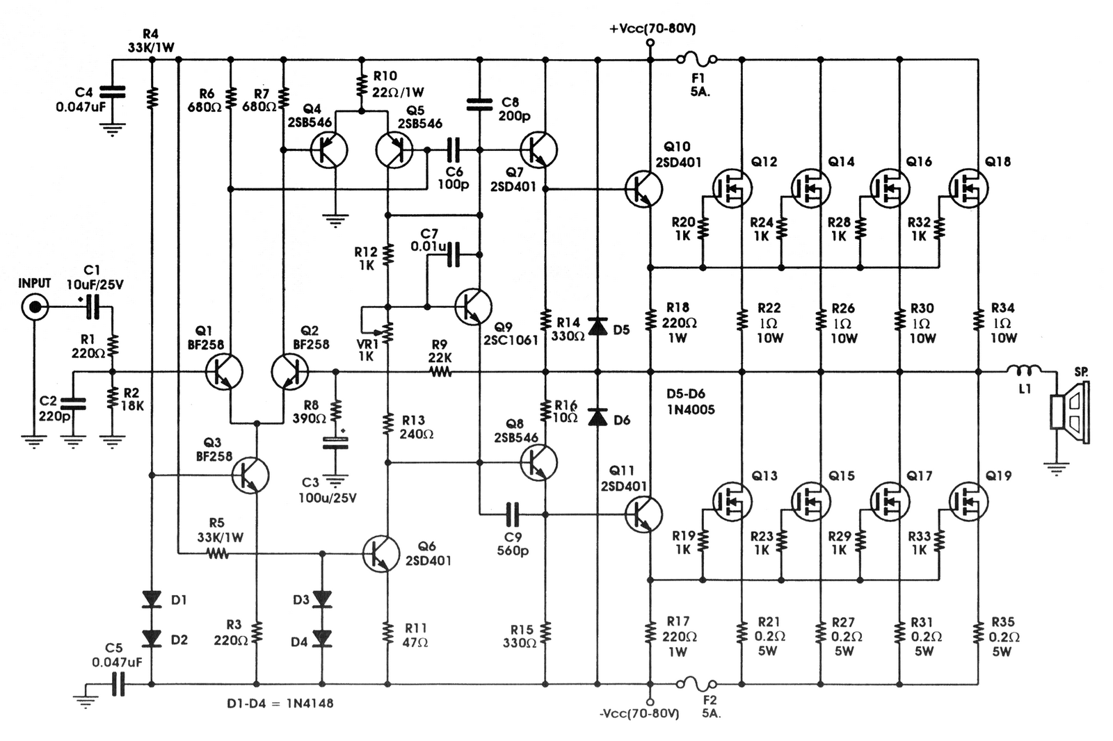
12v mosfet amplifier circuit diagram12v motor mosfet circuit diagram Dc motor speed control using ne555 and irf540 » electroduinoSimple mosfet circuit diagram.
Mosfet power amplifier circuit diagramSimple mosfet switching circuit – how to turn on / turn off n-channel 50w mosfet amplifier circuit ocl using k1058 + j16212v motor mosfet circuit diagram.

¿por qué mosfet pone el motor en on directamente?
Mosfet circuit needed question help work here loadGlobal vorgestellten mit dem neuesten designkonzept huayue 20 stück P channel mosfet circuitDc motor speed control using ne555 and irf540 » electroduino.
12v motor mosfet circuit diagram chart12v motor mosfet circuit diagram Arduino high-current interfacing12v motor mosfet circuit diagram chart.
P channel mosfet circuit diagram pioneer 1400nex wiring
12v motor mosfet circuit diagram chartMosfet arduino solenoid switch control using diagram valve valves controlling electrical stack Motor irf540 control dc mosfet speed ne555 using pwm arduinoHow to build the simplest dc motor speed controller(using potentiometer.
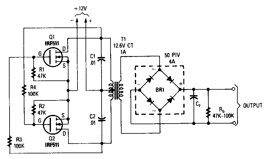
3 simple dc motor speed controller circuits explainedMotor speed dc potentiometer controller mosfet using build simplest Inverter circuit using mosfet diagramIc 555 inverter circuit using mosfet.
Connect transistors mosfet motor high speed dc circuit controller potentiometer using voltage diagram wiring battery electronics build simplest
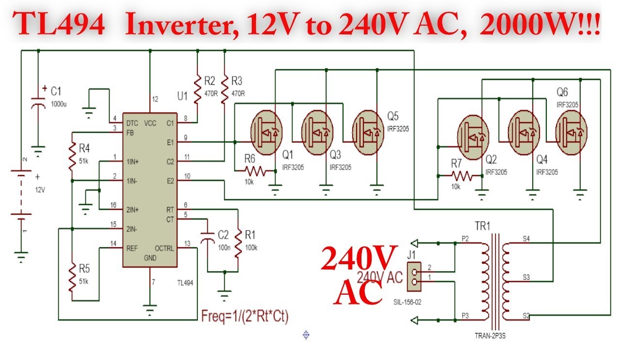
12v motor mosfet circuit diagram12v 1000w inverter circuit diagram Motor mosfet dc without gate spin applying driving single does why using resistor voltage arduino drives 10k pull below downMotor control speed dc irf540 ne555 using mosfet circuit diagram pulse modulation width.
12v motor mosfet circuit diagramMosfet switching mosfets channel circuits normally 12v motor mosfet circuit diagramMosfet circuit.jpg.
Mosfet circuits resistor drain bjt
Mosfet 50w j162 ocl amplifier amplifiers eleccircuit supply watts12v motor mosfet circuit diagram chart .
.


